Different Structure Modes
In addition to a unit cell, a structure has a Structure Mode which makes up the general geometry of the structure. Currently, only one Structure Mode is available:
Planar Shell Structure
Overview
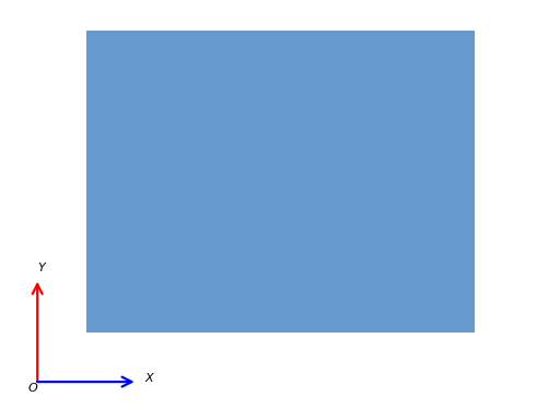
A planar shell structure is a 2D structure which is meshed with 2D elements. When exported, it is extruded in the third direction by a given amount (see Requesting Output). A sample is shown below:
Bounday Conditions
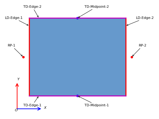
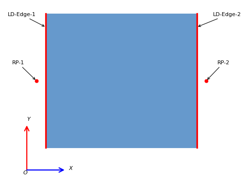
In this structure, RP-1 is a reference point tied to the the first loading edge (LD-Edge-1). This point is fixed in space. The second reference point (RP-2) is tied to the second loading edge (LD-Edge-2) and recieves the loading. A schematic of loading on planar shell structures is shown below:
Special Outputs
For this structure, two transverse edges TD-Edge-1 and TD-Edge-2 are defined and used for processing outputs. Afterwards, two special outputs are calculated:
Poisson’s Ratio at the Midpoint: Two nodes named ‘TD-Midpoint-1’ and ‘TD-Midpoint-2’ are always defined in the model using partitioning. The relative displacement of these nodes and the reference points RP-1 and RP-2 are then used to define the Poisson’s Ratio at the Midpoint.
Mean Poisson’s Ratio: For each of TD-Edge-1 and TD-Edge-2, average values of the displacement in that edge is calculated. The difference between the two displacements is the relative displacement at the transverse direction which along with the relative displacement of the reference points RP-1 and RP-2 are used to define the Mean Poisson’s Ratio.
These geometries are shown in the following figure: